The subject of this Chapter is prompted by several questions over the last couple of months concerning the alignment of tube lenses to high power microscope objectives. In most microscopes these days the objectives are designed as finite to infinite conjugate optics so there is a need for a “tube” lens to focus the object onto the eyepiece reticle plane or camera sensor array. Since the light is in collimated space between the objective and tube lens it would appear at first glance, the worst you would do with misalignment is vignette. However, when the requirement is for 50 or 100x magnification, even the slightest misalignment leads to loss in imaging performance.
Another use for high magnification microscopes is as part of an optical scanning system where the microscope is used backwards to move a well-focused spot across what would be the object plane of the microscope as used for viewing small objects. Here alignment affects not only the imaging performance but the linearity of the scan with angle of the input light beam. Schematic examples of both situations are shown in Fig. 1.

Fig. 1 Schematic of an infinite conjugate microscope used for viewing (upper), and a similar microscope used for scanning a spot over the image plane (lower)
We will frame the alignment question in terms of how the tube lens should be positioned relative to the objective in angle and lateral position. The spacing between objective and tube lens is flexible if it is within the design range of the tube lens, but 100 mm is a typical value. I find it easier to discuss examples using specific parameters so let’s use the following: the objective is nominally 100 x with an efl of 2 mm designed to work with a tube lens with a 200 mm efl placed about 100 mm from the entrance pupil of the objective.
Since the objective will serve as the reference for alignment, we must consider how its five degrees of freedom (DOF) are determined optically and mechanically. Fig. 2 shows typical mounting dimensions for one brand of objectives. The flange, a plane annulus nominally perpendicular to the objective’s optical axis controls angle in 2 DOF and the distance along the axis, 1 DOF. The thread diameter controls the objective’s position perpendicular to the axis in the remaining 2 translational DOF.
The threads are the weak point in this connection because every time you remove and reinsert an objective it moves laterally a few microns in a non-repeatable way. For ordinary viewing it doesn’t matter if the image shifts, but at 100 x with the tube lens 100 mm away a 1 um objective lateral shift causes an image shift of 100 um and an angular change of the collimated beam of almost 2 minutes of arc.
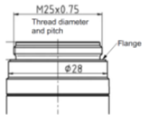
Fig. 2 A typical specification for the threaded interface of a microscope objective.
My understanding is that the threads are designed to have a little slop so that seating against the flange is definite. Given that the flange is a solid interface, this points to an approach to alignment. A plane parallel fixture with a bore and internal threads to match the objective is made parallel to an Axicon grating projecting a Bessel beam as in Fig. 3. The Figure gives all the steps to full alignment.
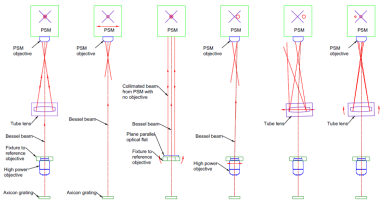
Fig. 3 The steps to align a tube lens with a microscope objective starting with a fully aligned system (a) to show the various required parts of the setup
Detail a) of Fig. 3 shows the completely aligned system so I can explain the various parts of the setup and their purposes. Starting at bottom is an axicon grating illuminated by a point source to produce a Bessel beam that acts as the reference axis for alignment. The beam propagates through the high magnification objective that is screwed into a fixture that provides a mechanical reference for the objective’s location. The beam continues through the tube lens where it is viewed with a Point Source Microscope (PSM). The monitor for the PSM is shown schematically with its reference crosshair. In the fully aligned condition, both the Bessel beam and a reflection from the center of curvature of a spherical surface within the tube lens are both centered on the PSM crosshair.
Detail a) makes it clear that in the first step of alignment b) the PSM must be at the correct axial distance to view the center of curvature of an element of the tube lens once it is inserted. With the PSM at the correct distance, the PSM is translated perpendicularly to the Bessel beam to center the beam on the PSM crosshair.
Next c), a fixture is added to the setup into which the objective will be mounted. The fixture is precisely parallel so the a plane parallel window or mirror set on the upper surface will be parallel to the flange against which the objective is mounted. The objective is removed from the PSM so it acts as an autocollimator and the fixture is squared to the Bessel beam and PSM by rotation. The fixture assures the objective is held so that is axis is parallel to the Bessel beam within the precision of the objective itself.
Once the fixture is adjusted, the objective is mounted in the fixture and the objective replaced on the PSM. The fixture/objective pair is translated laterally to bring the Bessel beam onto the PSM crosshair as in detail d). Here we have shown a slight misalignment of the objective and how that moves the Bessel beam centroid off the PSM crosshair in detail d). Once the Bessel beam is on the crosshair, the objective serves as the reference to which to align the tube lens. Because of the high magnification of the objective its lateral position is located to sub-micron precision. Again, the weak point in the alignment is that removing and replacing the objective in this fixture, or in the end item mount, is the lack of repeatability of the threaded interface.
With the objective set as the reference, the tube lens is inserted in the beam. Initially the lens is misaligned and the reflection from the center of curvature may miss returning in the objective. The Bessel beam may also be misaligned, but this is easy to correct because the rings in the Bessel beam show the direction to move the lens to center the core of the beam by translation as shown by the red arrows in e).
The final step in the alignment f) is to tilt the tube lens until the center of curvature is also centered on the crosshair. There may be a bit of iterative alignment to get both spots on the crosshair as the tilting may misalign the Bessel beam and vice versa. However, the procedure converges rapidly to position the tube lens to the 1 um level perpendicular to the beam and the 1 second of arc tilt range.
If your system is designed for observing, the alignment is complete. If you have a scanning system, the scan lens is aligned following the same principles since the Bessel beam is again centered on the PSM crosshair as it was before introducing either the objective or tube lens and it is propagating with the same angle. The beam is now used as the reference to move the PSM farther up to a place where it is focused at the center of curvature of a surface in the scan lens. Once the PSM is centered, the procedure is used the same way to align the scan lens.
USA

Innovations Foresight
4432 Mallard Point,
Columbus, IN 47201 USA
Telephone:
1-215-884-1101
Contact:
Customerservice@
All Asian Countries Except China
![]()
清 原 耕 輔 Kosuke Kiyohara
清原光学 営業部 Kiyohara Optics / Sales
+81-3-5918-8501
opg-sales@koptic.co.jp
Kiyohara Optics Inc.
3-28-10 Funado Itabashi-Ku Tokyo, Japan 174-0041
China

Langxin (Suzhou) Precision Optics Co., Ltd
1st floor, Building 10, Yisu Science and Technology Innovation Park, 100 meters west of the intersection of Xinhua Road and Weimeng Road, Kunshan City, Suzhou City, Jiangsu Province, 215345
Telephone: +860512-57284008
Contact: Wang Zengkun
+8617090133615
wangzengkun@langxinoptics.com