Chapter 16 – Footnote for Chapters 14 and 15
This brief chapter serves as a vital addendum to the last two chapters. While I’ve already described the alignment process, I realized I hadn’t emphasized how remarkably simple it is—and what makes it so effortless. Over the years, countless methods have been used to align optics successfully, long before Bessel beams entered the picture. What makes this approach truly stand out isn’t just its precision, though it certainly delivers that—it’s the unparalleled ease and speed with which it is done.
Let me begin with a brief review. We create and project a Bessel beam as a reference axis. We view the beam using a Point Source Microscope (PSM), and it is aligned to the PSM reference crosshair. We assume that the crosshair has been pre-aligned using a Cat’s eye reflection so that it is conjugate with the point source in the PSM.
The alignment task is to insert an optical system into the Bessel beam such that the beam is undisturbed from its initial condition, that is, the beam propagates through the system with no change in position or angle. This means the optical axis of the optical system must be coaxial with the Bessel beam reference axis. Because we must align an axis, we must be able to view two points along the axis that are separated axially; the farther the separation, the more sensitive we are to the misalignment of the axis.
Traditionally, this was accomplished using an alignment telescope, which was first focused at one point, and the system moved to bring the point onto the crosshair. Then, it was focused on the second point, where that position was aligned. Because, in practice, you seldom rotate or translate about optimum locations due to hardware constraints, the alignment proceeds gradually as one step slightly misaligns the previous step. And because of the refocusing between steps, you tend to forget which direction you moved in the previous step once removed; you often find yourself repeating yourself, sometimes going backward. The process is tedious, frustrating, unproductive, and prone to error.
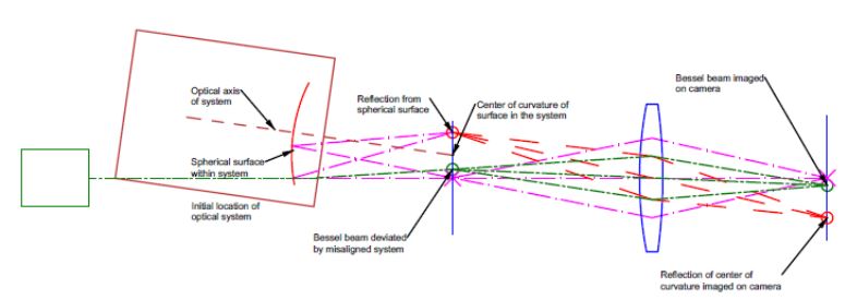
When using the Bessel beam and PSM combination, the Bessel beam is visible on the PSM camera anywhere along the beam. In addition, the PSM generates a point source at the focus of the objective. As the PSM is moved along the Bessel beam, the focus of the objective can be positioned at the center of curvature of an element in the optical system. When it is focused there, a reflection from the center of curvature is also visible on the camera. This gives two spots associated with the system undergoing alignment to work with simultaneously. These concepts are illustrated in the schematic figure below.

This figure schematically represents the PSM aligned to the reference Bessel beam prior to the insertion of the optical system to be aligned to the beam. The electronic crosshair is aligned to the stigmatic focus of the light exiting the PSM objective to < 1 um precision by viewing a Cat’s eye reflection off a specular surface. The PSM is then centered to the Bessel beam to 1 um precision at an axial location that is conjugate to an accessible center of curvature in the system to be aligned to the Bessel beam. Once this initial alignment of the Bessel beam/PSM pair is complete, the system to be aligned is inserted between the projector and the PSM, as in the next diagram.

Inserting the system deviates the Bessel beam, so it is no longer centered on the PSM crosshair. Additionally, the light from the PSM’s stigmatic focus is reflected in the system’s spherical surface. It refocuses on the PSM focal plane displaced from the stigmatic focus because the system is tilted relative to the initial Bessel beam axis. These two spots are reimaged on the camera displaced from the electronic crosshair. It is now a matter of translating the system to bring the Bessel beam to the crosshair and then tilting the system to bring the reflection from the spherical surface to the crosshair. This tilting will slightly move the Bessel beam from the crosshair, so the alignment process must be iterated. However, we have shown that the process converges to the PSM’s resolution limit in 3 to 4 iterations. In the end, we have the situation pictured below.

The center of curvature and the Bessel beam lie on the PSM crosshair and are coincident at the objective focus with the exiting stigmatic focus to < 1 um on the PSM with a 10x objective.
Seeing both spots simultaneously makes it significantly easier and faster to center them to the reference crosshair of the PSM. Because the system’s geometry is the same as using an alignment telescope, the movement of the spots with adjustments to the system may still be confusing. The spots may move in opposite directions as the optical system is adjusted, or one spot may move much faster than the other. However, it is easy to make small adjustments and continuously track both spots without touching the PSM.
This allows you to focus exclusively on aligning the system in translation and tilt with direct, real-time feedback, which is the most important advantage of the PSM/Bessel beam method. The continuous, direct feedback from both spot positions makes the method fast and completely deterministic while maintaining or improving the precision of using an alignment telescope. If you go to this 1 minute YouTube video https://youtu.be/UKSTej0Xt5k you can see just how fast the process is. The clip is taken out of context so there is no audio, but you can see the Bessel beam initial and then the spot from the center of curvature. The brief pause was to correct the relative intensities of the spots and change the screen so you can see the x,y coordinates of the centroid of the spots on the screen in µm.