Chapter 15: Tabletop Alignment Part 2
In Chapter 14, we showed how to determine the axis of a laser beam to which we want to align optical elements and then how to align a Bessel beam to the laser beam axis. This Chapter shows the steps to align optical elements to the reference Bessel beam. With tabletop alignment, you have all five degrees of freedom necessary to achieve complete alignment in translation and tilt. The only constraints to eliminating all alignment errors are the resolution of your alignment metrology instrument and the mechanical resolution and stability of your optical mounts.
Although you can achieve full alignment on a tabletop, the process is more complex than placing lenses in a cell because the lens cell explicitly defines some of the degrees of freedom that constrain the lenses. Often, these constraints make it impossible to achieve full alignment in an assembly of lenses. On the tabletop, although you have all the necessary degrees of freedom, you must have a procedure and methods of providing datums for the five degrees of freedom required to get full alignment. This Chapter explains the procedure and methods.
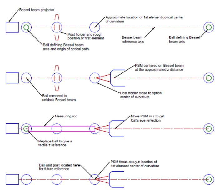
Figure 1 schematically shows the steps required before aligning the first element in a chain of elements. Following this overview, we will break the procedure into individual steps and explain each. To keep this simple, the example assumes a 2-element, 3:1 beam expander starting with the positive element. Once we have covered the initial preparations, we show the element’s alignment to the reference axis.

Fig. 1 Alignment steps before inserting the 1st element, shown in its intended position in dashed lines into the Bessel beam
In Chapter 14, we had the Bessel beam projector aligned to the laser beam axis. From our plan to introduce a 3:1 beam expander, we know that the optical center of curvature of the lens’s first surface must lie on the axis of the Bessel beam at a specific z distance along the beam. Fig. 2 shows the preparation for this step, where we roughly locate a post holder for the 1st element and another for the ball at the optical center of curvature using the tapped holes in the tabletop and a ruler for guidance.

Fig. 2 Post holders roughly centered on the Bessel beam axis the approximate z distances required
Once the post holders are located and secured, we align a PSM to the Bessel beam in x, y, as in Fig. 3, with its focus above the center of a post in the holder for the ball.

Fig. 3 The PSM is centered on the Bessel beam after removing the ball blocking the beam
With the PSM centered on the Bessel beam to < 1 µm in x and y, the reference ball near the projector is replaced on its post to serve as a tactile reference to establish the z distance to the optical center of curvature as in Fig. 4.

Fig. 4 Establishing the correct z distance to the optical center of curvature
The measuring rod in Fig. 4 could be a custom rod with square ends just for this spacing, an inside micrometer, or calipers. The measuring device or rod should be held in a stable mount for the most precise spacing. The lens post holder could be used temporarily for this purpose. When the rod touches the reference ball, the PSM is moved in z until the Cat’s eye reflection from the rod end is in good focus. Now, the PSM focus defines a point in space accurate to 1-2 µm in three degrees of freedom that will be the location of the optical center of curvature of the lens’ 1st surface when the lens is inserted.
Then, remove the ball and measuring rod to ensure the PSM is still well centered in x and y. Since this will be a reference for the beam expander, adjusting a post and ball here for the future is good practice, as in Fig. 5. There is no need for an adjustable mount. The post holder may be tapped into position using the two degrees of freedom provided by the tabletop, and adjusting the height by squeezing the post with thumb and finger against the top of the post holder, as in pulling a tooth, after slightly loosening the locking screw. With a little patience, this can be done with a precision of a micrometer or two.

Fig. 5 Ball located at the optical center of curvature of the first surface of the positive element
Now, the PSM focus is located in three degrees of freedom, ready for the positive element to be inserted. Notice that the PSM defines five degrees of freedom for the lens, two degrees for the x, y location of the Bessel beam transmitted through the lens, and, separately, in three degrees that define the optical center of curvature.
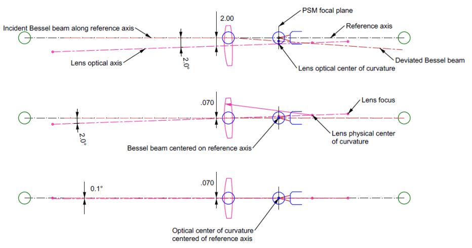
Fig. 6 shows the situation when the lens is inserted and then the first iteration of alignment. We show a case where the lens is inserted 2 mm decentered and 2° tilted. You can probably do better than this by eye, but then it would be difficult to illustrate the alignment in the Figure.

Fig. 6 The first lens is inserted in the Bessel beam and the first iteration of alignment
The inserted lens’s tilt and decenter cause the Bessel beam to deviate, so the PSM sees the beam below the reference axis. The optical center of curvature lies farther from the reference axis. The first alignment step is shown in the middle view when the lens was moved upward 1.93 mm so that the Bessel beam is centered to the PSM to < 1 µm. This first step of centering the lens leaves the vertex of the first surface 0.07 mm below the reference axis and moves the optical center of curvature above it by 0.405 mm because the lens’s tilt is unchanged.
In the lower diagram, we tilt the lens 1.9° to bring the optical center of curvature so it is centered to the PSM. It looks in the figure like we are about done. However, because the vertex of the lens is 0.07 mm below the reference axis, there is still about 0.1° of tilt, which makes the Bessel beam decentered by 11 µm below the axis. We can do better by repeating this same sequence of alignment operations until the Bessel beam and optical center of curvature are < 1 µm from centered to the PSM.
Since the process converges rapidly, about a factor of 3 to 4 per iteration cycle, and the PSM is not touched during the alignment process, the lens alignment is faster than preparing to do the alignment. Just three to four cycles of alignment center the lens to < 1 µm and < 1 second of arc. This means the Bessel beam is deviated by no more than this so it is used as the reference axis for inserting the negative lens in the beam expander.
Several details need to be mentioned. We have assumed the lens mount rotates the lens about its first surface, where most 5-degree-of-freedom mounts pivot. The convergence ratio depends on where this pivot lies and is fastest when the pivot is in the plane of the lens’s second surface. During the centering and tilting, the adjustment screws will shift the z distance of the lens, leading to a defocus. Your adjustable lens mount should have an adjustment screw at the pivot point, making it fully a five DOF mount so the z spacing can be controlled by adjusting all three screws and correcting the defocus.
I finish this Chapter on 5 degree of freedom lens alignment by referring you to a video of this type of alignment, but in a different context. The video shows the meniscus half of a cemented doublet being aligned before adding the positive element for cementing. During the alignment, the seat for the meniscus is centered by tapping to align the lens in translation. At the same time, it is rotated or tilted by sliding it on the seat, again by gentle tapping, to bring the center of curvature centered to the PSM.
In the video, you will see that tapping sometimes overshoots, but with a little patience, you can center the seat to 1 µm and get the tilt to about 1 arc second, depending on the radius of the surface in the seat. Further, there is instant eye/hand feedback, so it is immediately obvious where the next tap should go. It is also evident that the process could be automated should the quantity of lenses warrant the expense.
https://vimeo.com/818873649/d7b8444277 Fast-forward to 14:30 to see the lens first inserted into the Bessel beam, then go to 16:00 to see additional centering. Open the video to full screen so you can see the numbers showing the centration in µm. Once you watch the video part, you may want to read the introductory material that explains the full process and why there are constraints when centering lenses in a cell.