Chapter 14: Tabletop Alignment Part 1
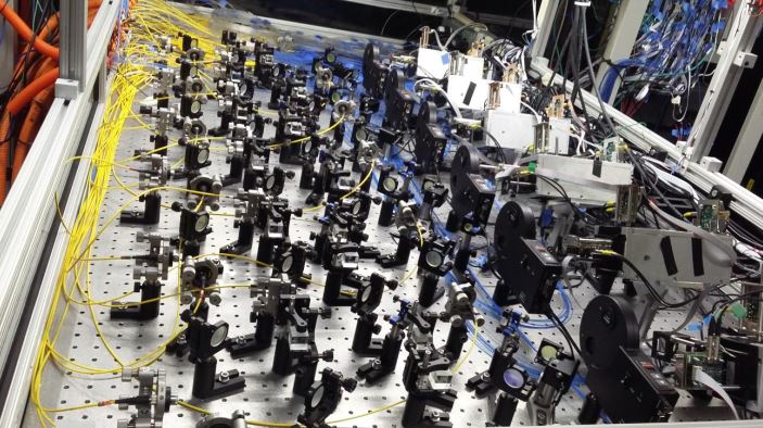
At last, I am back to writing more about optical alignment. The hiatus was due to my realization that most readers are not interested in assembling lenses in a tube. Rather, they want to align free-standing optics on tabletops or benches in labs researching topics like laser light interactions with matter, free-space communication, and quantum computing. The picture below shows what I mean. It took time to rearrange my thoughts.

(Picture credit: Figure 2 from Anastasi, A., Basti, A., Bedeschi, F., Boiano, A., Bottalico, E., Cantatore, G., Cauz, D., Chapelain, A.T., Corradi, G., Dabagov, S. and Di Falco, S., “The laser-based gain monitoring system of the calorimeters in the Muon g−2 Experiment at Fermilab”, Journal of Instrumentation, 14(11), p. P11025, (2019))
To achieve maximum performance from such tabletop laser systems, that is, to get the maximum irradiance (W/m2) on the target, the optics must be aligned to tolerances that approach or surpass those for lenses in a cell. However, finding references to the precision alignment of such tabletop systems is difficult. The break in writing was to investigate this type of alignment where it is impossible to use an axis of rotation as a reference axis.
The investigation led to several constructive conclusions: with tabletop alignment, you always have the 5 degrees of freedom to align the optical axis of a component to your reference axis, which is often limited to only 2 or 3 degrees of freedom in the case of lenses in a cell. This means you can achieve perfect alignment to the resolution limits of your ability to adjust the optics and your alignment detection system. Further, the method of alignment using a Bessel beam has already been shown effective and reported [1], but not in the context of tabletop alignment. The method is perfectly suited to tabletop alignment. Finally, Glen D. Gillen’s well-written tutorial introduction to tabletop alignment is freely available online [2]. I encourage reading this as it has many practical tips to consider before starting benchtop alignment.
To start the alignment of getting a laser beam from a source to a target, we must find the laser beam’s axis and then align our reference Bessel beam axis to it. Next, we must generate the Bessel beam to align the first lens in the path using an autostigmatic microscope. This chapter will cover these two topics and leave the lens alignment for Chapter 15.
Aligning a Bessel beam to a laser beam
For a low-power laser, use a quadrant detector to locate the center of the beam at two locations along the beam. Once the quadrant detector is centered on the beam, bring an autostigmatic microscope up to it and center the PSM on the intersection of the quadrants. Remove the quad cell and replace it with a ball on a post so the center of the ball is at the PSM focus. The ball marks one point along the beam. Repeat this with the quad cell at a second location along the beam and use the PSM to position a second ball at the center of the quad cell. Now, the path of the laser beam is known in position and angle.

Left, center of quad cell as seen by the PSM. The gap between quadrants is 100 µm, and the white spot in the middle of the gap is the Cat’s eye reflection from the cell surface as seen through the imperfect window on the quad cell. Right, the PSM objective focused on the quad cell intersection. Then, the quad cell is removed, and a ball is centered on the objective focus to transfer the location of the cross.
Sidebar: Use quad cells wisely, at 45° to the tabletop. Then, the beam location is the difference of the opposing quadrants. This is easier than placing the quad cell square with the table where the voltages from pairs of quadrants must be added before they are differenced, as seen in the figure.

For a high-power laser, burn a spot in a card placed in the beam and use the PSM to focus on the center of the burn spot. Use the PSM to position a ball as in the quad cell case. As with the quad cell, a second spot along the beam must be found to establish the beam axis. Now, the two balls define the axis of the laser beam.
Sidebar: Note that a quad cell is useless for centering a Bessel beam. Because the energy in each ring is the same as the core, or any other ring, the average intensity of the Bessel beam is essentially constant, so the quad cell sees little change as the Bessel beam moves across it.
Creating and aligning the Bessel beam
Although Bessel beams were discussed in Chapter 9, I did not specifically say how I was producing them. I use chrome on glass zone plates (equally spaced, concentric circles) made by photolithography techniques [3] with 20 µm line pair spacing to give a diffraction angle of about 1.8° when illuminated with 635 nm light. The zone plate is illuminated with a single-mode optical fiber located about 200 mm behind the grating. This set of conditions produces a Bessel beam that starts within a few µm of the grating and extends for meters with a 25 mm diameter grating.
Catalog item Axicons also create Bessel beams, which single-mode fibers can illuminate to produce long Bessel beams. I prefer fiber rather than collimated illumination because no collimating lens is needed, making the setup simpler and allowing the Bessel beam to propagate farther. Also, I like the grating zone plate because it is easier to align the beam normal to the grating, and the grating also serves as a plane mirror in its zero-order mode. Either way, an Axicon or zone plate grating defines 5 degrees of freedom with one optical element.
We return to the two balls defining the laser beam to align the Bessel beam with the laser beam axis. Assuming the balls are mounted kinematically (see Sidebar) to be removed and replaced repeatably, the PSM is focused on the center of the ball farthest from the Axicon or grating. Then, the ball is removed, and the Bessel beam projector is rotated until the Bessel beam is centered on the PSM. The ball nearest the projector is placed on its mount, and the PSM is centered on the ball, and the ball is removed. Then, the projector is translated to bring the BB onto the center of the PSM. This cycle is repeated until the beam is centered on both balls. The process is a bit tedious. However, since it is possible to center the beam to <1 µm and if the balls are 200 mm or more apart, the BB will be coaxial with the laser beam to .002/200 = 1e-5 = 2 arc seconds.
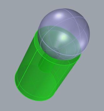
Sidebar: An easy way to mount balls that define mechanical datums is to set them on the ends of lens posts used for mounting stand-alone optics. The lens posts typically have a countersunk conical bore, as in the picture, that serves as a seat for a ball of roughly the same diameter as the post. With good quality balls the center of the ball will repeat its location to < 1 µm each time it is removed and replaced. By good quality ball, I mean Grade 5, round to 125 nm. If worse quality balls are used the reflected image may seem displaced by more than the repeatability of the kinematic mounting. There are precision, magnetic holders designed for use with the SMR retroreflectors employed with laser trackers for non-vertical locations. These mounts, or nests, are expensive compared to lens posts.


The line figure shows the horizontal laser axis (red line) and the Bessel beam axis at the start of the alignment (black line). The numbers show how the alignment proceeds by rotating the axis to the ball farthest from the point of rotation until the axis is aligned with the ball, step 1, and then translated to align with the near ball, step 2, etc. The convergence occurs rapidly, even though the PSM has to be moved between iterations.
Once the reference Bessel beam is aligned with the laser axis, we are ready to align lenses to the beam, the subject of Chapter 15.
References
[1] R. E. Parks, Precision cementing of doublets without using a rotary table, Proc. SPIE, 11487OU (2020)
[2] Gillen, Glen D. “Laser Laboratory Beam Alignment Skills: Course Package.” arXiv preprint
arXiv:2404.16225 (2024).
[3] Bessel beam zone plates are made by Arizona Optical Metrology, LLC, https://aom.us/
USA

Innovations Foresight
4432 Mallard Point,
Columbus, IN 47201 USA
Telephone:
1-215-884-1101
Contact:
Customerservice@
All Asian Countries Except China

清 原 耕 輔 Kosuke Kiyohara
清原光学 営業部 Kiyohara Optics / Sales
+81-3-5918-8501
opg-sales@koptic.co.jp
Kiyohara Optics Inc.
3-28-10 Funado Itabashi-Ku Tokyo, Japan 174-0041
China

Langxin (Suzhou) Precision Optics Co., Ltd
1st floor, Building 10, Yisu Science and Technology Innovation Park, 100 meters west of the intersection of Xinhua Road and Weimeng Road, Kunshan City, Suzhou City, Jiangsu Province, 215345
Telephone: +860512-57284008
Contact: Wang Zengkun
+8617090133615
wangzengkun@langxinoptics.com
Copyright ©
Website by CS Design Studios
Headquarters: 7011 E Calle Tolosa, Tucson, AZ 85750
Laboratory: 1661 S Research Loop, Tucson, AZ 85710
