News & Announcements for January 2021
GOOD NEWS FOR THE NEW YEAR, THE STANDARD PSM WORKS IN THE NEAR IR
Many times potential customers have asked “How far does the PSM work into the infrared?” I told them the standard PSM works as far out as 1050 nm with the CMOS camera that comes with every new PSM because I have used the PSM there with a fiber coupled external source. But some customers want to go farther into the IR.
PART 1: EXPERIMENTS WITH IR CAMERAS

USING THE PSM TO SEE THROUGH SILICON
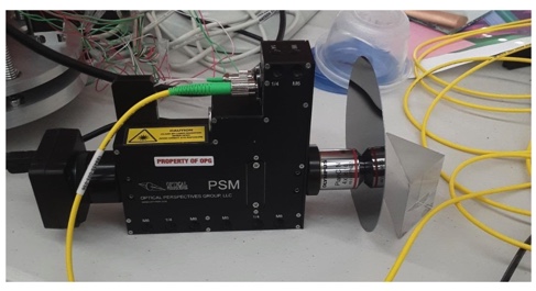
Recently we purchased a camera that is sensitive out to 1600 nm and a laser source at 1550 nm to see if we could use the PSM to see through silicon. It works! We did the most simple minded experiment of putting a silicon wafer between the PSM objective and a front surface plane mirror as in the photo.
This shows that with an external laser source and a fairly inexpensive NIR camera the standard PSM is useful for aligning lenses containing silicon optics. It had been my worry that one of the lenses in the PSM, or a beamsplitter coating, would prevent the PSM from working at this wavelength. The standard PSM works just fine with the addition of the NIR C mount camera.
Some people, however, want to look through germanium that becomes transparent at 1900 nm or so. The inexpensive NIR camera does not work for this. But the question for me remained, is there something in the PSM or objective that would block light in the region that germanium transmits. Mark Christenson, a representative of Envisionate offered to get a Xenics Xera 2.35 camera to try out with the PSM. With a 6 mm uncoated germanium window sitting in front of the objective we could see the filament of an incandescent heat lamp, see below.

IMAGE OF A HEAT LAMP FILAMENT VIEWED THROUGH A 6 MM GERMANIUM WINDOW WITH THE PSM
This is hardly a sophisticated experiment but it proves there is nothing in the PSM that prevents use of a camera sensitive out to 2350 nm. This is not an inexpensive camera, but if you already own a PSM, you can simply screw this camera on to the PSM C mount and bring in a fiber coupled source at around 2 um and be ready to align lenses with germanium optics. In this case, Optical Perspectives is not going to purchase the camera for you, but if you have or can borrow a camera, we will provide a PSM so you can demo the idea in your facility.

XENICS XEVA 2.35 CAMERA C MOUNTED TO THE PSM
The picture of the PSM mounted on the camera looks like the tail wagging the dog, but if that is what it takes, this is a solution to looking through germanium optics.
PART 2: PRECISION LOCATION OF CGHS
A METHOD OF PRECISELY LOCATING A COMPUTER GENERATED HOLOGRAM (CGH)
When using computer generated holograms (CGHS) to test aspheres and freeform optics it is essential that the CGH be precisely located relative to the interferometer transmission sphere and the optic under test. This location is often done with 3 balls mounted to the CGH to form a kinematically repeatable method of mounting the CGH. One of the limits to the precision is how well the balls align with the CGH pattern. We have a way of aligning the balls within a micrometer of their optimum location using the PSM provided there is a little planning in the design of the CGH.
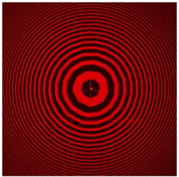
In a prior paper* we talked about writing Fresnel zones on CGHs to simulate concave spheres for alignment purposes. If these Fresnel zones are written at the time the CHG null pattern for the asphere is written the zones will be within 10’s of nm of the desired location. We showed in the paper how a PSM is used to position a ball to a μm of the center of the Fresnel zone. As described in the paper the method of attaching the balls is it is awkward to implement.
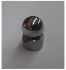
A much better method is to use readily available Spherically Mounted Retroreflector (SMR) nests (used with laser trackers) to hold the balls. These nests have a magnet, a plane back and a precise cone to hold a precision ½” diameter ball. This makes a stable mount for the ball, it is easy to slide the nest/ball pair into place on the CGH and provides for good bonding to the CGH. The pictures below show the idea.

THIS PICTURE SHOWS JUST THE NEST AND A GRADE 5 CHROME STEEL BALL

THIS PICTURE ABOVE SHOWS HOW THE BALL AND NEST ARE POSITIONED OVER THE SMALL FRESNEL ZONE PATTERN THAT ACTS LIKE A CONCAVE MIRROR WITH A RADIUS OF CURVATURE JUST EQUAL TO THE HEIGHT OF THE CENTER OF THE BALL SITTING IN THE NEST
To position the nest/ball pair, the PSM picks up the center of curvature of the Fresnel zone and is adjusted so the reflected spot is well centered on the PSM crosshair. Then the nest/ball pair are slid into place so the ball center is centered on the crosshair. Now the ball center is precisely centered over the Fresnel zone pattern within 1 μm and the nest is cemented in place.

THREE NEST/BALL PAIRS PRECISELY POSITIONED ON A 6” PHOTOMASK SUBSTRATE AND CGH PATTERN
The finished CGH looks like this image with three nest/ball pairs ready to be set in a kinematic mount.
This method has several distinct advantages over some others.
First, the ability to position each of the balls within a μm of the precise location using the CHG pattern and the PSM.
Second, the SMR nest makes a stable platform on which to hold the ball while positioning it prior to cementing as opposed to the method shown in the paper.
Once the nests are bonded the balls are removable so there is a minimum of height above the CGH surface and the nests are held securely in place. An added advantage is that the position of the CGH can be determined either using a CMM and touch probing the balls, or the ball can be replaced with ½” SMRs and located with a laser tracker.

MICROPHOTOGRAPH OF THE CENTER OF THE FRESNEL ZONE PATTERN USED FOR POSITIONING THE NEST/BALL PAIRS
* Parks, R. E., “Optical Alignment using a CGH and an autostigmatic microscope”, Proc SPIE, 10377, 103770B, (2017), available in the Downloads>Bibliography accessible from the button below.
USA

Innovations Foresight
4432 Mallard Point,
Columbus, IN 47201 USA
Telephone:
1-215-884-1101
Contact:
Customerservice@
All Asian Countries Except China

清 原 耕 輔 Kosuke Kiyohara
清原光学 営業部 Kiyohara Optics / Sales
+81-3-5918-8501
opg-sales@koptic.co.jp
Kiyohara Optics Inc.
3-28-10 Funado Itabashi-Ku Tokyo, Japan 174-0041
China

Langxin (Suzhou) Precision Optics Co., Ltd
1st floor, Building 10, Yisu Science and Technology Innovation Park, 100 meters west of the intersection of Xinhua Road and Weimeng Road, Kunshan City, Suzhou City, Jiangsu Province, 215345
Telephone: +860512-57284008
Contact: Wang Zengkun
+8617090133615
wangzengkun@langxinoptics.com
Copyright ©
Website by CS Design Studios
Headquarters: 7011 E Calle Tolosa, Tucson, AZ 85750
Laboratory: 1661 S Research Loop, Tucson, AZ 85710
