Although this is a chapter on off-axis parabolas (OAPs), I want to start with one more way of testing symmetric parabolas because it illustrates a point about off-axis alignment. Assume we have a symmetric parabola with no central hole and we want to minimize the obstruction due to testing. If we set the parabola up in front of an interferometer with a reference transmission flat, then we can place a ball centered on the focus to give a double pass test as in Fig. 1.

Fig. 1 Symmetric parabola in front of an interferometer transmission flat
The blue curve is the parabola, and the red lines are rays normal to the reference flat (magenta) reflecting off the parabola to the green ball used as a convex spherical mirror. The shorter radius black circle matches the radius of curvature of the parabola at its vertex and shows that the parabola’s radius of curvature gets longer as you move to the edge of the parabola. This is why you need a null lens to test a parabola at its center of curvature.
The longer radius black circle has its center of curvature at the 7/10ths zone of the parabola, or where a normal from a zone 7/10ths (sqrt(2)/2 of the way to the edge) intersects the axis of the parabola. If you were not using a null lens, this is where you would focus to minimize the difference between the parabola and a spherical wavefront. All this may seem off the subject until we ask how we should align the parabola in front of the interferometer?
As in Chapter 17, we know that 3 degrees of freedom of alignment are satisfied when the light from the interferometer is centered on the ball. In terms of fringes, this means no tilt fringes, the exact equivalent of light returning centered of the crosshair of the PSM when it is the test device. The rest of the alignment for the remaining two degrees of freedom concerns the most efficient way to adjust the parabola to remove the aberration, coma in this case, of a symmetric parabola.
Fig. 2 shows the misaligned parabola with the light still centered on the ball. The Figure is far enough misaligned so some aspects are not exact, but exaggeration was necessary to show the point about which the parabola must be rotated to keep alignment with the ball, namely about the intersection of the normal to the edge of the parabola and its optical axis.
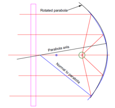
Fig. 2 Symmetric parabola aligned to a ball at its focus but rotated about the intersection of the normal to the edge of the parabola and its optical axis
The black line is the axis of the rotated parabola, and the blue line is the normal at the ray intersection close to the edge of the parabola. The small blue circle is the center of curvature of the vertex of the parabola at twice the focus distance. You can see the close to zero match at both edges and the center of the parabola and the “S” shaped, or coma, departure at roughly half the zonal radius of the parabola. Rotating about the intersection of the normal at the 7/ths zone and axis the parabola brings it into alignment with the flat to remove the comatic aberration while not shifting the focus off the center of the ball. The intersection is at the sagittal focus of the parabola for the zonal radius indicated by the blue line.
If you are testing a single parabola there is not much readily available hardware that lets you rotate about the sagittal focus, so you must iterate translation and tilt to achieve alignment. However, if you are doing production alignment, then it makes sense to custom design a fixture that lets you rotate about this point to achieve rapid alignment.
When we think about an off-axis parabola, the symmetry about the optical axis is broken, and the point about which we rotate for alignment is not the sagittal center of curvature, but the tangential center which lies on the normal but off the axis of the parent off axis parabola [1].
When we align an off-axis parabola the usual method is just as in the case of the symmetric one, use a focused beam at the focus of the OAP and have the light collimated by the OAP reflect off a plane mirror to the OAP and back to the focus. It looks so simple in a drawing like Fig. 3. In practice, it is maddeningly frustrating unless you have thought through the process thoroughly, and even then, it is hard. There are several things you can do to make it easier.
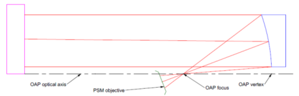
Fig. 3 OAP tested at its focus
Use a low power objective on the PSM at the OAP focus so you have a large field of view to capture the reflected light. Keep the plane mirror as close as possible to the OAP to minimize the length of the path back to the OAP and thus the decenter of the reflected path. (Once you are aligned, it is easy to move the plane mirror back away from the OAP to give you more room because the OAP and PSM establish the axis to the plane mirror.) Adjust the distance between the focused light source and the OAP to give approximately collimated light reflected from the OAP on the first reflection. Of course, use an aluminized plane mirror because you need all the light you can get to see the beam reflected from the plane mirror. Dimming the lights in the lab also helps.
Once the reflected light is approximately centered on the OAP you will see the focused spot in the vicinity of the focused spot exiting the objective. Continue to make small adjustments until light enters the objective. Now you can center the aberrated blob of light on the PSM crosshair to know that the light is normally incident on the plane mirror. Now make a small compensating tilt of the plane mirror and decenters of the PSM to keep the blob of light centered and well-focused while reducing the size of the aberrated image. It is easier to make the initial adjustments so the aberrated image is aligned to the axis of one of your adjustments and then shrink the image size by adjusting in the other axis. Continue until the spot is as small and round as possible.
The process of tilting the plane mirror and moving the PSM is effectively rotating the combination of mirror and OAP around the tangential radius of curvature of the OAP. If the OAP is mounted with 5 adjustments, it can be moved around the same point while the PSM and plane mirror stay fixed.
If there are space constraints, or other reasons, the OAP can be aligned by placing a ball at its focus and using the PSM as an autocollimator as in Fig. 4 that is an off-axis version of Fig. 1. During the initial setup adjust the PSM and OAP to get as round as possible light spot on a white card at the parabola focus before inserting the ball. Then adjust the ball in 3 DOF to get light back in the PSM. Continue adjusting the ball until the aberrated image is centered on the crosshair.
The order of making the initial adjustments may have to be changed if the center of the ball must be at a specific location relative to other features of the test setup. In some cases, not only will the ball location be fixed but the direction of the collimated beam is fixed so that all five degrees of freedom must be adjusted using the OAP.
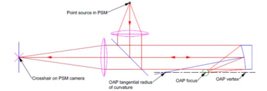
Fig. 4 PSM used as an autocollimator for OAP alignment
Notice there is a 6th degree of freedom, but it has relatively loose tolerances in most cases. This degree of freedom keeps the beam centered on the clear aperture of the OAP to avoid vignetting. This is important but not to the 1 um and 1 arc second level necessary to eliminate aberrations.
With the spot centered on the crosshair of the PSM in autocollimator mode, it is easy to see whether the spot is in best-focus and whether it is aberrated because the illumination is a point source. The routine for final alignment is the same as before. Compensating tilt and decenter motions are made on the OAP to keep the spot centered and in focus while reducing the aberrations to get a small, round spot centered on the crosshair.
This method of using the PSM as an autocollimator to align the OAP may be more difficult to align initially but it may be the only option when there is a small space in a vacuum chamber or similar apparatus. The good news is that there is a way of performing precise alignment where it would be close to impossible any other way.
That is all for now, but we will have some future discussion about aligning conic optics using the focus and radius of curvature. This way you do not have to rely on aberrations but can set the axis of the OAP to a precise position.
[1] Smith, W. J., Modern Optical Engineering, 3rd. Ed., p. 485, McGraw-Hill, NY, (2000).
USA

Innovations Foresight
4432 Mallard Point,
Columbus, IN 47201 USA
Telephone:
1-215-884-1101
Contact:
Customerservice@
All Asian Countries Except China
![]()
清 原 耕 輔 Kosuke Kiyohara
清原光学 営業部 Kiyohara Optics / Sales
+81-3-5918-8501
opg-sales@koptic.co.jp
Kiyohara Optics Inc.
3-28-10 Funado Itabashi-Ku Tokyo, Japan 174-0041
China

Langxin (Suzhou) Precision Optics Co., Ltd
1st floor, Building 10, Yisu Science and Technology Innovation Park, 100 meters west of the intersection of Xinhua Road and Weimeng Road, Kunshan City, Suzhou City, Jiangsu Province, 215345
Telephone: +860512-57284008
Contact: Wang Zengkun
+8617090133615
wangzengkun@langxinoptics.com