I often receive requests for assistance with aligning parabolic mirrors, particularly off-axis ones. Interestingly, with the right tools, the actual alignment process is often quicker than mounting the optical alignment equipment. This observation led me to reflect on the tools themselves. Currently, no traditional method—whether using an autocollimator or an alignment telescope—provides an effective way to align a parabola with a plane mirror.
In this chapter, I will explore the practical alignment of parabolic mirrors, beginning with full, rotationally symmetric mirrors and progressing to off-axis mirrors in the following chapter. The focus will be on practical approaches and techniques, rather than the theoretical concepts typically found in textbooks.
A parabolic mirror perfectly images collimated light to a focus if the optical axis of the parabola is perfectly coaxial with the incident light. In practice, what is wrong with this statement? The instrument at the focus obscures some to all the incident light, depending on the size of the mirror. It is easy to draw Fig. 1a in a textbook, but it does not show the actual situation in Fig. 1b, let alone Fig. 1c, with a small mirror.
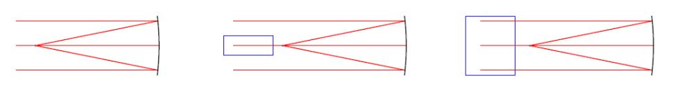
Fig. 1 a, light from infinity coming to a focus. Fig. 1 b, light is partially blocked by the test instrument; Fig. 1 c, light is blocked by the test instrument, as might be the case for a small mirror.
For the same practical reasons, we assume that a symmetrical parabola—such as the one used in a Newtonian telescope with a diagonal plane mirror to bring the focus outside the telescope—results in some degree of obscuration. The difference between the practical use in the telescope and testing the uncoated parabola right off the polishing machine is that the test instrument is larger than the diagonal mirror unless the parabola is larger than the ones in most amateur telescopes.
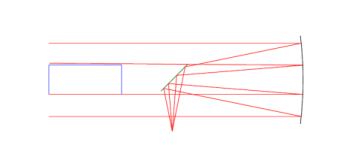
Fig. 2 Symmetric parabola focused as in a Newtonian telescope to show that the obscuration of the diagonal may be less than that due to the test instrument (blue rectangle)
It is clear from Fig. 2 that we can reduce the obscuration due to the diagonal for test purposes by moving it farther from the parabola so the test obscures less of the aperture than when used as a telescope.
Another practical test problem is how to simulate light from infinity. Once the aperture of the parabola is larger than about 100 mm, the cost of the collimator used for testing is more than the cost of making the parabola. This expense is why we test most parabolas in double pass off a plane mirror, a less costly test arrangement for a large symmetric parabola. As parabolas get larger, they usually have a hole around the vertex since this mirror part is obscured. The hole opens many test options, as in Fig. 3, where there is no longer an obscuration due to the test instrument. Another advantage is that the test instrument has a light source producing heat. When the instrument moves outside the test path, the heat-produced turbulence problem goes away.
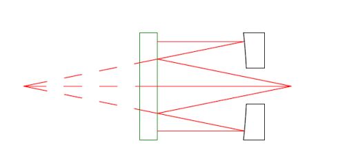
Fig. 3 Parabola with a central hole tested against a plane mirror
The plane mirror must be high quality as the light path hits it three times. The mirror must also be highly reflective since the parabola under test will usually be bare glass. The light is incident on it twice, so only 0.16% of the initial light is reflected into the test instrument. If the test instrument is an interferometer, a standard transmission sphere designed for use with bare glass will not produce high-contrast interference fringes. On the other hand, if the test instrument is an autostigmatic microscope such as a PSM, there is plenty of light to align and analyze the image.
Fig. 3 shows the test in perfect alignment, but that is not the situation when we first set the plane mirror and parabola on an optical table for testing. The situation will be like that shown in Fig. 4, where the point source of light at the PSM focus reflects back displaced and out of focus.
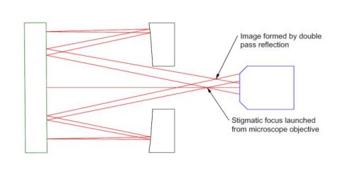
Fig. 4 Same as Fig. 3 except slightly misaligned by tipping the plane mirror and shifting in axially
Fig. 4 assumes the plane mirror was rotated 0.4 ° about its vertex and shifted axially toward the microscope objective of the PSM. The reimaged focus is shifted laterally and axially due to the misalignment. In addition, the nominally parallel rays from the parabola are no longer normally incident on the plane mirror. This detail illustrates the first step in aligning a parabola; we move the PSM until the reimaged focus lies on the crosshair of the PSM and is in focus. When this condition is met, the collimated light from the parabola is normally incident on the plane mirror. This first step of the alignment only locks down 3 degrees of freedom because all we see is a single point at the reimaged focus. The remaining 2 degrees of freedom account for the aberrations in the reflected image.
It is clear from Fig. 4 that if we move the PSM objective upward about half the lateral separation of the foci and to the right slightly, the reimaged focus coincides with the focus of the light launched from the PSM. However, since we did not move the parabola, its axis remains 0.4 ° non-normal to the plane mirror and causes aberrations in the image. If we rotate the flat to remove the aberrations, the reimaged focus will move off the PSM crosshair. To reach complete alignment with no aberrations, we move the PSM laterally as we rotate the plane mirror to keep the reimaged focus centered on the crosshair. It is evident when you adjust in the right direction because the aberration, coma for a symmetric parabola, will decrease as we gradually move the mirror and PSM to keep the image centered. A simple way to see why you get aberrations even though the rays are incident on the plane mirror at normal incidence is to consider Fig. 5a, where rays from infinity are incident on the parabola so that the rays and parabola optical axis are parallel. Fig. 5b shows the parabola rotated about its vertex by 1°. This rotation moves the focus below the ray incident on the mirror’s center. It appears this is all that has happened until you look closely, as in the detail around the focus in Fig. 5c, where the ray from the center in the parabola is 13 µm above where the marginal rays focus, producing an aberrated image.
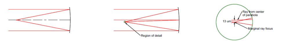
Fig. 5 An aligned parabola, left, parabola rotated 1° to incident rays, middle, and a 70x detail of the immediate region around the focus showing the spread in rays due to the misalignment.
Here is a good place to recap what we discussed about aligning a symmetric parabola to a plane mirror where we assume we have a central hole in the mirror. Using the setup in Fig. 3, we can precisely locate the parabola in 3 degrees of freedom by assuring the return reflection is in focus and centered on the PSM crosshair. We remove the remaining 2 degrees of freedom using aberrations. When I say the return image is centered on the PSM crosshair, I am saying that the centroid of the aberrated image is centered on the crosshair. This determination gets more precise as we adjust the setup to remove the aberrations, consequently making the image smaller and rounder.
We are constrained to using aberrations for the remaining two degrees of freedom because we do not have information about the plane mirror relative to the PSM. However, we can measure the tilt of the PSM to the mirror by using it as an autocollimator by removing the objective, as shown schematically in Fig. 6.
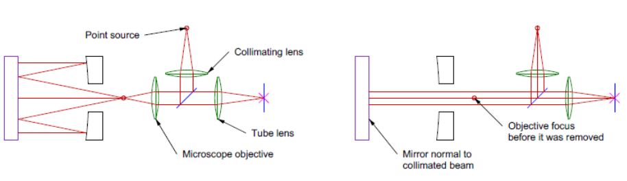
Fig. 6 Aligning parabola in all 5 degrees of freedom with a PSM by using it as both an autostigmatic microscope with an objective and as an autocollimator without the objective
All five degrees of freedom are accounted for since we define a line or an axis by a point and two angles. The only position where the parabola can be located—while still reimaging the point of light at the PSM objective focus and ensuring it is centered on the PSM crosshair—is when the parabola’s axis is perpendicular to the plane mirror. Practical considerations also come into play: the PSM must be securely mounted to prevent movement when the objective is removed, there must be sufficient space behind the parabola to facilitate objective removal, and the objective must consistently screw into its holder without causing lateral shifts. Typically, lateral shifts are less than 5 µm, meaning that if the parabola’s focal length exceeds 500 mm, the resulting error from such shifts is less than 1 second of arc. Now that we have covered the alignment of symmetric parabolas both by using aberrations and 5 degrees of freedom, we will cover off-axis parabolas in Chapter 18. In some ways, they are easier to align than symmetric ones because you don’t have to worry about obstructing the beam.